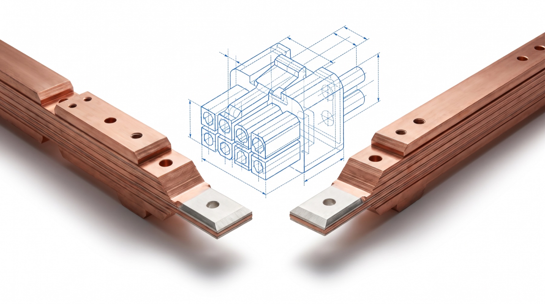
There is a new number running through the AI buildout: 800 VDC — eight hundred volts, direct current.
NVIDIA announced the architecture. Dozens of companies attached their names to it. Press releases call it an ecosystem. Analysts call it a transition. Conference panels call it inevitable.
So we went looking for the standard. Not the narrative — the standard. The thing a standard is actually made of: a connector drawing. A pin sequence. A busbar profile with tolerances. A grounding diagram. A test you can run to prove two vendors’ hardware will mate.
It doesn’t exist.
That finding sounds like a criticism of 800 VDC. It isn’t. The physics behind the transition is real, and we’ll walk through it. The finding is something more useful. It tells you where the actual asset is in this transition — and it is not where the press releases are pointing.
The audit
Start with the roster. Our audit registered 44 named ecosystem companies, which reconcile to 41 distinct entries once grouped and overlapping entities are combined. We scored each entry against a simple bar: does the public record contain an engineering artifact a hardware team could actually use? A versioned specification. A schematic. A component datasheet. A mechanical interface document.
Nine clear the bar. About twenty-two percent.
41 classified ecosystem companies. 9 usable engineering artifacts.
Each square is one classified company. The bar for the top tier: a versioned spec, schematic, datasheet, or mechanical interface document in the public record — something a hardware team can build against.
Versioned OCP specs, reference schematics, component datasheets, a mechanically specified connector.
Named products, power figures, whitepapers, roadmaps — no interface drawing, pinout, or public certification package.
Collaborations, facility claims, conference material, broad positioning.
No verified 800 VDC-specific public artifact located.
44 named companies reconcile to 41 classified entries once grouped and overlapping entities are combined; 9 of 41 — about 22% — clear the usable-artifact bar. Tiers grade public engineering disclosure by named ecosystem participants, and top-tier artifacts include adjacent 48 V-class documents (the OCP hyperscaler specs, Dell’s ORv3 design, Amphenol’s BarKlip). No company in any tier — none — has published a finalized 800 VDC rack-inlet interface specification. Research date: August 2026.
And the distribution of that engineering is upside down. The companies that publish real artifacts are semiconductor vendors and the OCP hyperscalers — the parts layer and the open-spec layer. The companies expected to deliver the actual rack-to-power interface — the architecture owner and most of the power-system integrators — publish architecture claims and partnership language.
The roster also has false positives, and they are telling.
When “800” isn’t volts
Three products that drift into 800 VDC ecosystem counts on the strength of a model number.
When a category is hot enough, a model number becomes a membership card. None of the three should count in a qualified 800 VDC supplier tally without a voltage-specific design package. “False positive” refers only to these specific part numbers — it does not mean LITEON or Great Wall Power Technology lack genuine 800 VDC capability; both separately market or develop 800 VDC data-center power products under other model names. Starline’s B800 remains excluded because its published rating is 600 V AC/DC.
Here is the sharpest version of the finding. As of mid-2026, no UL or IEC certification could be found as granted for any 800 VDC-specific data-center product category. Not a rack-input connector. Not a busbar. Not a distribution board. Not a switchgear lineup. (General-purpose 1,500 VDC breakers do exist under PV- and battery-oriented listings — they are not a data-center interface certification.) A buyer of a “ready” 800 VDC solution today may actually be buying a multi-party engineering exception process. That can be a reasonable choice in a well-scoped pilot. It is a very different thing when it arrives buried inside a lump-sum design-build package.
The ask hidden in the whitepaper
The most important evidence comes from NVIDIA itself.
To be clear about what NVIDIA has published: real block-level engineering. Its reference design describes a 17.5 megawatt power block — five 3.5 MW rectifiers converting 35 kV AC to 800 VDC in a five-to-make-four arrangement, feeding a 5,000 amp central DC board, with 1,500 amp busducts running to four 1.1 megawatt compute racks. Its developer blog claims 85 percent more power through the same conductor than 415 volt AC — the whitepaper’s fixed-conductor table puts the same comparison at 157 percent — plus 45 percent less copper, and up to five percent better end-to-end efficiency than today’s 54 volt systems.
Those are serious numbers. Now look for the interface underneath them.
NVIDIA’s 17.5 MW block is real engineering — down to one missing document
The published grid-to-rack chain, as specified in NVIDIA’s 800 VDC whitepaper. Every block carries numbers. The last interface carries none.
Specified in the whitepaper: rectifier sizes, redundancy scheme, board and feeder ampacities, per-rack feeds. Not specified: connector name or part number, mechanical drawing, pitch, keying, terminal numbering, busduct cross-section, rack mounting interface, final grounding drawing.
The whitepaper does not name the rack-input connector. No part number. No mechanical drawing. No pitch, no keying, no terminal numbering. No final grounding diagram. It calls its designs “not rigid specifications, but rather illustrative examples” — and then it asks the industry to “establish standardized … connector interfaces.”
Read that twice. The company defining the 800 VDC narrative is publicly requesting that a standard be formed. That is not evidence a standard exists. That is evidence one doesn’t.
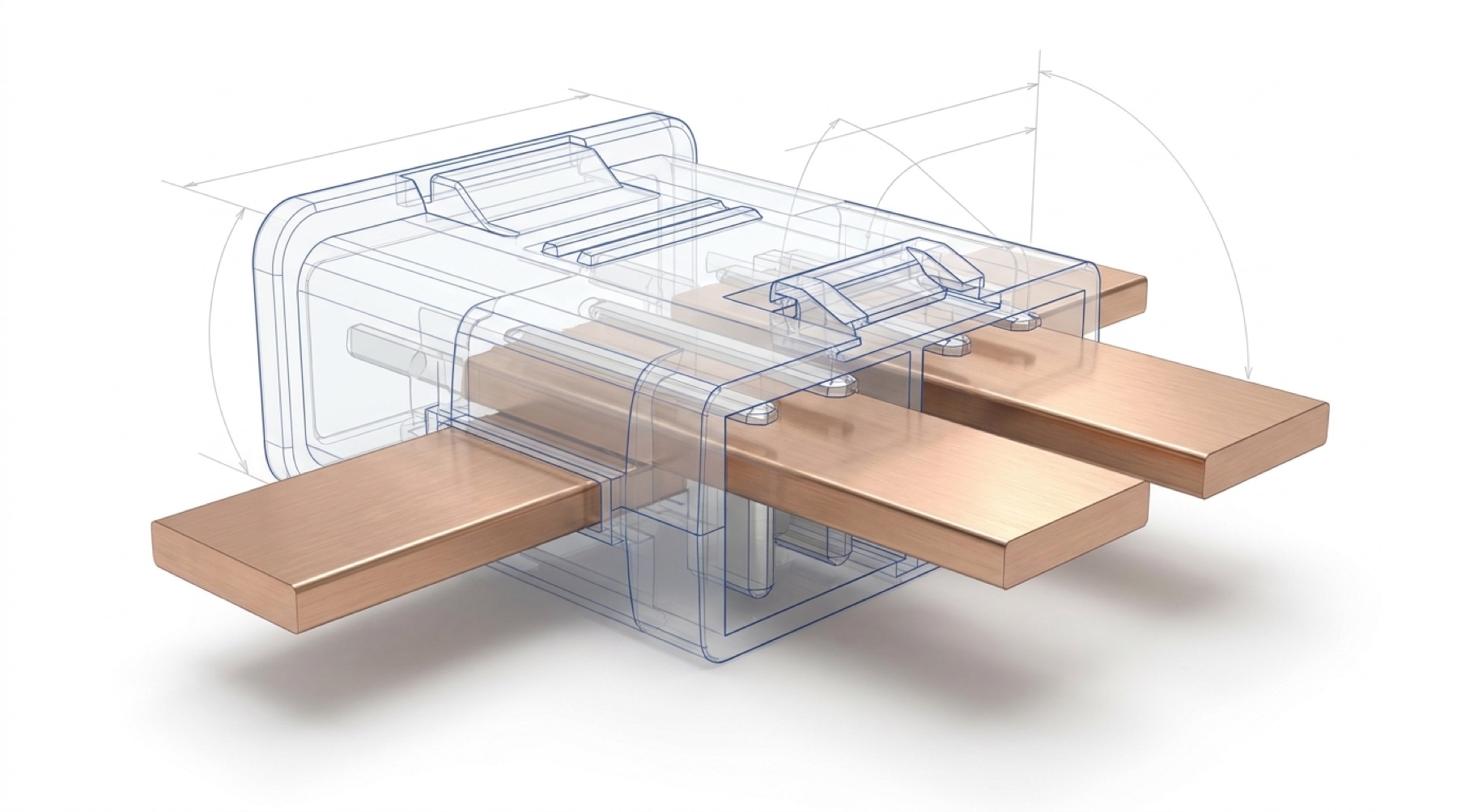
There are commercially sensible reasons for the silence. Reference designs run ahead of products, and a published part number freezes decisions suppliers are still changing. But one reason deserves particular attention: a physical power interface controls the upgrade path, the service tooling, the warranty boundary, and every second-source negotiation that follows. The absence of a public interface document is not an oversight. It is a position.
One label, two incompatible systems
It gets one layer worse. “800 VDC” is currently two different systems.
NVIDIA’s path is monopolar: a positive 800 volt conductor, a return, and protective earth. Two wires and a ground. The open-compute path — authored by Google, Meta, and Microsoft — defaults to bipolar: positive 400, negative 400, and a midpoint conductor. Three wires, different grounding options, different protection, a different sidecar design.
Same phrase. Incompatible metal.
Both camps say “800 VDC.” At the level of conductors, grounding, protection, and connectors, they are different systems.
The OCP specification permits a monopolar 800 V output option, and NVIDIA’s whitepaper says its rack can support multiple schemes — but connectors, earthing, and sidecar arrangements are not physically interchangeable between the two defaults. A vendor can say “800 VDC” while building for hardware that will not mate with another vendor’s “800 VDC.” Neither camp has published a finalized pole-count, interruption, and grounding specification for the rack interface.
Why the voltage is real anyway
None of this means the transition is hype. The transition is arithmetic.
Power is voltage times current. Hold the voltage at 54 volts — today’s in-rack standard — and watch what happens as racks scale. A 230 kilowatt rack, this year’s leading edge, draws about 4,259 amps. A 600 kilowatt rack, the next generation’s target, draws over 11,000 amps. A one-megawatt rack draws 18,519 amps.
Current per rack: 54 VDC vs 800 VDC
Ideal DC arithmetic, I = P ÷ V, at four rack-power classes. The 800 V bars are not small because the chart is unfair. They are small because that is the entire argument.
Ideal arithmetic before conductor geometry, contacts, derating, and redundancy. A 600 kW rack at 48 V implies ≈12,500 A — arithmetic popularized by SemiAnalysis, not an NVIDIA-published figure. Schneider Electric’s framing: 400 V three-phase AC and 48 VDC-to-rack distribution become difficult at 200 kW per rack and impossible at 400 kW.
So yes: the voltage will rise. The number is not the question. The question is what you can bolt to the wall today that will still be worth something when the number moves again.
What a real standard looks like
We know what a finished interface specification looks like, because the industry has one — at low voltage. The Open Compute Project’s Open Rack v3 defines its 48 volt connector with the kind of detail that makes hardware interchangeable.
ORv3 at 48 V vs the “800 VDC ecosystem”
Line by line: what the mature low-voltage interface publishes, against what the 800 V category has published as of August 2026.
| Interface element | OCP Open Rack v3 · 48 V | 800 VDC ecosystem |
|---|---|---|
| Connector drawing & mate geometry | ✓Blind-mate connector, mechanically specified | —Not published |
| Named part number | ✓Amphenol-authored spec; part/drawing numbers in the companion BarKlip datasheet | —None public |
| Misalignment tolerance | ✓±3 mm float | —Not published |
| Contact plating | ✓Wear-tested plated finish — “no exposed nickel or copper” | —Not published |
| Mate / de-mate sequencing | ✓Power-sense line gates energize & removal | —No public sequence document |
| Ground continuity & torque values | ✓100 A power/ground continuity, torque specified | —Not published |
| Certification / listing | ✓Established UL/IEC paths at the voltage class | —No granted 800 VDC-specific listing found |
Even the mature precedent carries a caution: ORv3’s own language makes the geometry that would guarantee cross-vendor busbar interchangeability a MAY, not a SHALL, and sets no formal external frame dimensions. “OCP-compliant” is a real engineering claim — it is not a compatibility guarantee.
That is what it takes. Drawings, tolerances, platings, part numbers, sequences, tests. If the industry’s most mature open rack interface stops short of guaranteed interchangeability at 48 volts, calibrate accordingly for what “800 VDC ecosystem” means at ten times the voltage — with the connector unpublished.
The building blocks, to be fair, exist in quantity. The connector industry has decades of high-current and high-voltage product families. What it does not have is a public decision about which building block, mechanical form, pilot logic, and protection architecture together constitute an interoperable 800 VDC rack boundary.
Credible components everywhere. A rack standard nowhere.
The named connector families closest to the problem — and the gap each one leaves.
| Family | Published capability | Gap for an 800 V rack standard |
|---|---|---|
| Amphenol BarKlip BK150 | The ORv3 IT-gear-to-busbar interface; 480 VDC component (dielectric) rating on a 46–52 V bus | No 800 VDC rating or public 800 V rack inlet |
| TE BB1000 | 46–52 VDC blind-mate; 360 A contact, up to 1,000 A system | A 48 V system, not a high-voltage standard |
| BizLink Rack Busbar | 48–54 VDC; 300–1,400 A classes | Production capacity at the current voltage class only |
| Molex PowerPlane | 130–320 A per circuit cataloged; liquid-cooled rack busbar to 15,000 A aggregate | No common 800 VDC mate, sequencing, or certification |
| Stäubli CombiTac uniq | 300 A contacts; IP2X; 100,000 mating cycles; modular power + fluid | No published standard 800 V rack-inlet configuration |
| Positronic Scorpion | Blind mate to 3.8 mm misalignment; ORv3 power-shelf input co-author | Low-voltage ecosystem contribution, not an HVDC standard |
| Amphenol Floating Mate | Up to 120 A at 1,000 VDC, or 1,500 VDC variants at 65 A; drawer-style blind mating | Current capacity and fault duty short of a MW rack feed |
| TE AMP+ HVP 800 | Automotive HV interconnect; 250 A; 650/850/1,000 V variants, IP67 — “800” is a family name | EV pedigree; no data-center rack interface, insufficient current |
The table proves the opposite of an excuse: suppliers hold every ingredient. The missing element is a public, cross-vendor decision — which is exactly the part that carries the commercial leverage.
The interface is the asset
Now the reframe this audit forces.
Infrastructure history says the durable fortune in any platform transition is rarely the headline parameter. It is the documented physical interface. Railroads compounded value once gauge was standardized — by law, cartel coordination, and installed-base network effects as much as by voluntary publication — so that any builder’s rolling stock could run on any operator’s track. Container shipping was not transformed by the box; it was transformed by the standardized corner casting — the fitting that let any crane, any ship, and any chassis handle any container. The winning move was never picking the right number. It was controlling — or committing early to — the interface contract that let generations of equipment change on top of an asset that didn’t.
The AI power transition has exactly this structure, and the numbers make it unusually stark.
Three asset clocks vs a one-year compute cadence
A hall’s assets live on three different usage-life clocks — and every clock you wait on is longer than the cadence of the racks it serves.
Nearly every hall now under design will commission into a different rack generation than the one it was drawn for. These are usage-life clocks, not tax-depreciation schedules. The operator’s exposure is not “which voltage wins” — it is whether the annual rack change lands as a swap or as a construction event. That is decided at the interface layer.
When the rack changes — and it changes nearly annually — is the response a rack swap or a construction event? That answer is decided entirely at the interface layer. Not by the voltage. By the busbar pitch and blade geometry. By the connector family and its approved alternates. By the mate sequence. By the earthing scheme and what must be isolated for service. By the protection zones that decide whether one fault drops one rack or one hall. By the tap-off ampacity that decides whether a distribution run can be re-tapped for a bigger rack — an accessory replacement — or must be torn out and replaced — a shutdown and a rebuild.
Every one of those is exactly the layer the current 800 VDC ecosystem has not published.
NVIDIA’s own transition plan concedes the point. Its whitepaper describes the 800 volt side power rack — the sidecar bolted next to the new high-density racks — as “an adapter to existing facilities”: a dedicated rack of rectifiers that converts the hall’s existing AC to 800 VDC locally, so the new racks can run in old halls today. The same document calls it “not the optimal solution end-to-end,” and says that as native DC distribution matures, the side power rack “can be replaced” by rectification upstream. Note what changes and what doesn’t: the compute rack’s voltage never moves — the adapter does. The industry’s own bridge architecture is a bolt-on, replaceable conversion module. That is exactly the design doctrine this essay argues an operator should own deliberately, rather than inherit by accident.
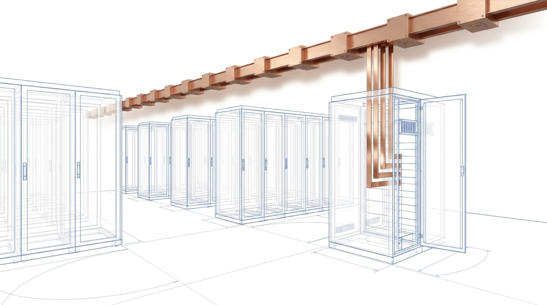
The physics of a swap
One more piece of engineering makes the point concrete, because “just hot-swap it” is doing a lot of unexamined work in this transition.
At 48 volts, plugging live equipment into a busbar is a designed, sequenced, well-understood service function. At 800 volts, the casual version of that idea dies on two facts of physics. First, DC has no zero crossing — 60 hertz alternating current passes through zero 120 times a second, and an AC arc can extinguish at those crossings; a DC arc has no natural zero, so something must force the current to zero. Second, a power converter’s discharged input capacitor looks like a dead short at the moment of contact; without a pre-charge circuit, insertion means uncontrolled inrush, arcing, and welded contacts.
The eight decisions hiding in one busbar mate
A schematic rack-to-busbar interface. Every callout is a controlled document in a real standard — and an open question in the current ecosystem.
In ORv3 at 48 V, most of these are written down. At 800 VDC the architectures and voltage options are public, but the rack-inlet geometry, mate sequence, and certification set are not. The eight elements are this essay’s interface-contract checklist, not a published industry taxonomy. Whoever writes them controls the upgrade path.
A high-voltage rack interface therefore isn’t a plug. It is a protocol.
“Hot swap” at high voltage is a sequence, not a plug
The no-load-mate procedure a controlled interface specifies — contractual, testable, and run in reverse for removal.
Latch & align
Mechanical latches engage; the module is restrained and aligned before any contact.
Earth proves first
Protective-earth contact establishes first; continuity is verified before anything energizes.
Pilot verifies
Pilot contacts confirm identity, voltage class, grounding state, and permission to energize.
Pre-charge ramps
A resistor path raises the capacitor toward bus voltage; the controller verifies the ramp.
Mains close
Main poles close only at near-zero differential voltage — never into a discharged link.
Converter enables
Only then may the downstream converter deliver energy to the load.
Removal runs in reverse
Load disables, mains open, discharge is verified dead, pilot drops — earth breaks last.
DC has no natural current zero, and a discharged DC-link capacitor is a short circuit at first contact. Serviceability at this voltage class means isolated-module replacement under interlock — engineered concurrency, not casual unplugging. The seven steps are an illustrative synthesis of documented first-mate/last-break practice and standard DC-link pre-charge design, not a codified industry standard.
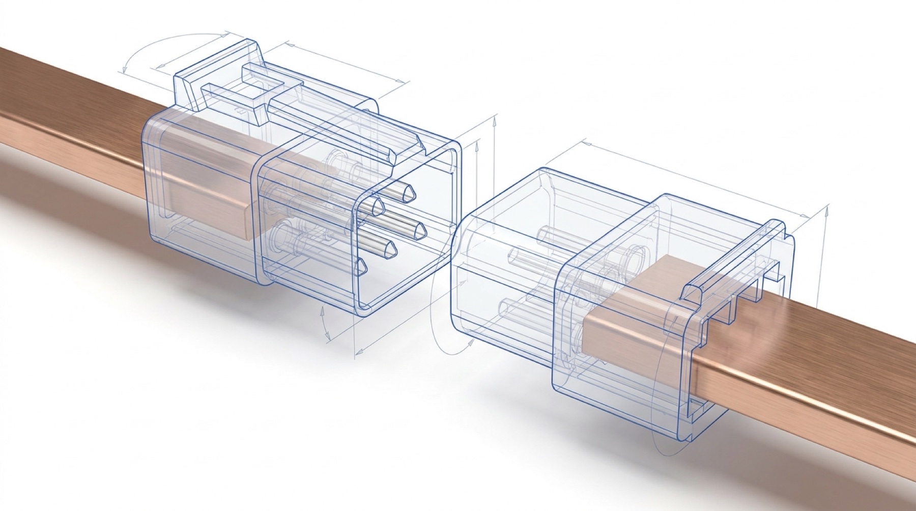
None of that is exotic. All of it is specifiable. And that is precisely the tell: the difference between an ecosystem and a standard is whether this sequence exists as a controlled document with a test you can run at acceptance — or as a slide.
The number above 800 is already forming
If you still suspect the voltage number itself is the durable thing, notice that the next number is already in motion.
Microsoft’s Azure engineering blog describes solid-state transformers that convert medium-voltage AC to DC voltages below 1,500 volts — component headroom, not a deployment roadmap. Trade coverage of an OCP working-group lead’s conference remarks says the architecture “could open the door” to future requirements up to 1,500. A 2026 engineering preprint models a plus-and-minus 750 volt busway — 1,500 volts line to line — for exactly this class of facility. And 1,500 VDC is not speculative as a voltage class: it has been the de facto utility-scale solar standard since roughly 2018, first deployed commercially in 2012, with a mature supply chain of breakers, connectors, and converters, sitting deliberately at the top of the international low-voltage envelope. Meanwhile, as of mid-2026 no commercial IT equipment has been found or announced that accepts more than 800 volts at the rack — so any higher plant voltage terminates upstream of the white space by definition.
The voltage ladder keeps climbing. The interface discipline is what persists.
Distribution voltage by era. Heights indicative, not to scale — this is a ladder, not an axis.
1,500 VDC is the top of the international low-voltage envelope (IEC 61140 / 60364 / 61439; the 2023 NEC’s Article 495 begins above 1,000 VAC / 1,500 VDC — Article 490 in earlier editions). As of mid-2026, no commercial ITE located in this review accepts more than 800 V at the rack — a higher collection voltage is a plant-side architecture with a step-down boundary, not a rack standard.
The details matter less than the direction. The industry’s number has moved from 12 to 48 to 54, is moving to 800, and has a visible candidate above that. Voltages are settling points in an argument that reopens every product generation. Interfaces — documented, tested, second-sourced interfaces — are what a twenty-year asset can actually be built on.
What to do about it
For an operator or developer, the audit resolves into a doctrine with four parts.
Split the asset from the argument
Design the long-lived layer — pathways, structure, electrical rooms, cooling, protection architecture, metering boundaries — to be indifferent to the outcome of the 800 V fork. Put the topology bet in a replaceable conversion module at the row boundary, where being wrong costs an adapter, not a hall.
Buy evidence, not adjectives
“800 VDC ready” is not a specification. The gate is a controlled drawing with a revision history, a rating on a datasheet, certification status stated separately from certification intention, a protection study with named settings, an acceptance test, and a written warranty boundary. A vendor who cannot produce those is selling a concept.
Write the interface document the market hasn’t
Where no public standard exists, the operator’s own interface-control documents — plant bus specification, row-conversion interface, mechanical envelope, mate-sequence and acceptance tests — become the standard for that facility. That is how the expensive assets stay yours to re-tenant across rack generations.
Treat missing certification as a schedule item
No granted 800 VDC-specific product certifications means the AHJ and the insurer are design reviewers, not rubber stamps. Engage them early, pilot in bounded cells with a rollback path, and let evidence — not a roadmap date — trigger each expansion.
The tell
Here is the compact version of everything above.
When a real standard exists, the boring documents exist: the drawing, the tolerance, the plating, the torque value, the mate sequence, the test. When only a narrative exists, the boring documents are missing and the adjectives are doing the work.
The 800 VDC transition is real. The physics guarantees it. What does not yet exist is the standard — the published, certified, cross-vendor interface that would let the industry’s most important power transition be bought rather than negotiated. Until it exists, every “ecosystem” claim should be read the way this audit read it: as a request for trust in place of a drawing.
The organizations that come through this transition owning something durable will not be the ones that guessed the right voltage. They will be the ones that noticed the standard didn’t exist — and wrote their own interface documents while everyone else was sharing the press release.
Questions operators ask
What is 800 VDC power distribution in AI data centers?
Is 800 VDC an official standard today?
How many companies have published real 800 VDC engineering?
Why are AI racks moving from 54 volts to 800 volts?
What is the difference between NVIDIA's 800 VDC and OCP's ±400 VDC?
What is a power sidecar?
Can you hot-swap an 800-volt rack?
What is a busway re-tap and why does it matter?
What voltage comes after 800 VDC?
What should an operator require from a vendor claiming 800 VDC ready?
Read next
Sources
Standalone sources pageEvery source on one page — grouped, linked, citableFindings and figures are drawn from a structured disclosure audit of the named 800 VDC ecosystem (44 named / 41 classified companies, August 2026 research date) and the primary engineering record. Every factual claim was re-verified against primary sources in an August 2026 fact-check pass; corrections from that pass are incorporated.
- NVIDIA, 800 VDC architecture whitepaper — 17.5 MW reference block; “illustrative” designs; the call to “establish standardized … connector interfaces”
- NVIDIA Developer Blog, 800 V HVDC architecture — conductor, copper, and efficiency claims
- OCP Open Rack v3 base specification — power-sense gating; MAY vs SHALL interoperability language
- OCP ORv3 power output connector specification — blind-mate, float, plating, named part number
- Signal Stack, OCP rack standards and interoperability — anonymous trade commentary; corroborating, not load-bearing
- Adi Kumar, “Two Architectures Wearing the Same Name” — monopolar vs bipolar fork; a named individual’s personal technical commentary, cited as such
- Siemens & NVIDIA (G. Yang, Siemens; M. Tu, NVIDIA), Protections for Data Centers Powered by Direct Current — DC fault behavior, grounding schemes
- Texas Instruments, pre-charge design note — DC-link inrush and pre-charge
- Molex, first-mate / last-break technical brief — contact sequencing
- LITEON RPG800-12AS datasheet and Great Wall GW-CRPS800N2 teardown — the 800-watt false positives
- Starline data-center busway portfolio — busway ratings; the 800-amp false positive
- TE Connectivity, ORv3 power solutions guide — BB1000 blind-mate system
- Amphenol FCI BarKlip BK150 datasheet — the ORv3 busbar interface
- Molex PowerPlane, Stäubli CombiTac uniq, Positronic OCP connectors, Amphenol Floating Mate, TE AMP+ HVP 800 — the connector building blocks
- BizLink Rack Busbar — 48–54 V production busbar classes
- Wolfspeed, 2,300 V SiC for 1,500 V DC-bus applications — semiconductor headroom above 800 V
- arXiv:2606.25095, ±750 VDC busway architecture — the voltage class above 800 in the engineering literature
- DatacenterDynamics, OCP members on DC power — “could open the door” to 1,500 VDC
- NVIDIA, Building the 800 VDC Ecosystem — partner roster and OCP Global Summit release timing
- Microsoft Azure Infrastructure Blog, Rethinking Power Conversion — SST headroom below 1,500 VDC
- Schneider Electric, The 1 MW AI IT Rack Is Coming — the 200 / 400 kW distribution thresholds
- SemiAnalysis, Inside the 800 VDC Revolution — 48 V current arithmetic at 600 kW
- Reuters, US Power Equipment Lead Times — GSU transformer leads past 160 weeks
- AI Data Center Guide, busway vs RPP — single-author technical guide; illustrative re-tap example, paired with manufacturer manuals for safety practice