How the block functions, in order
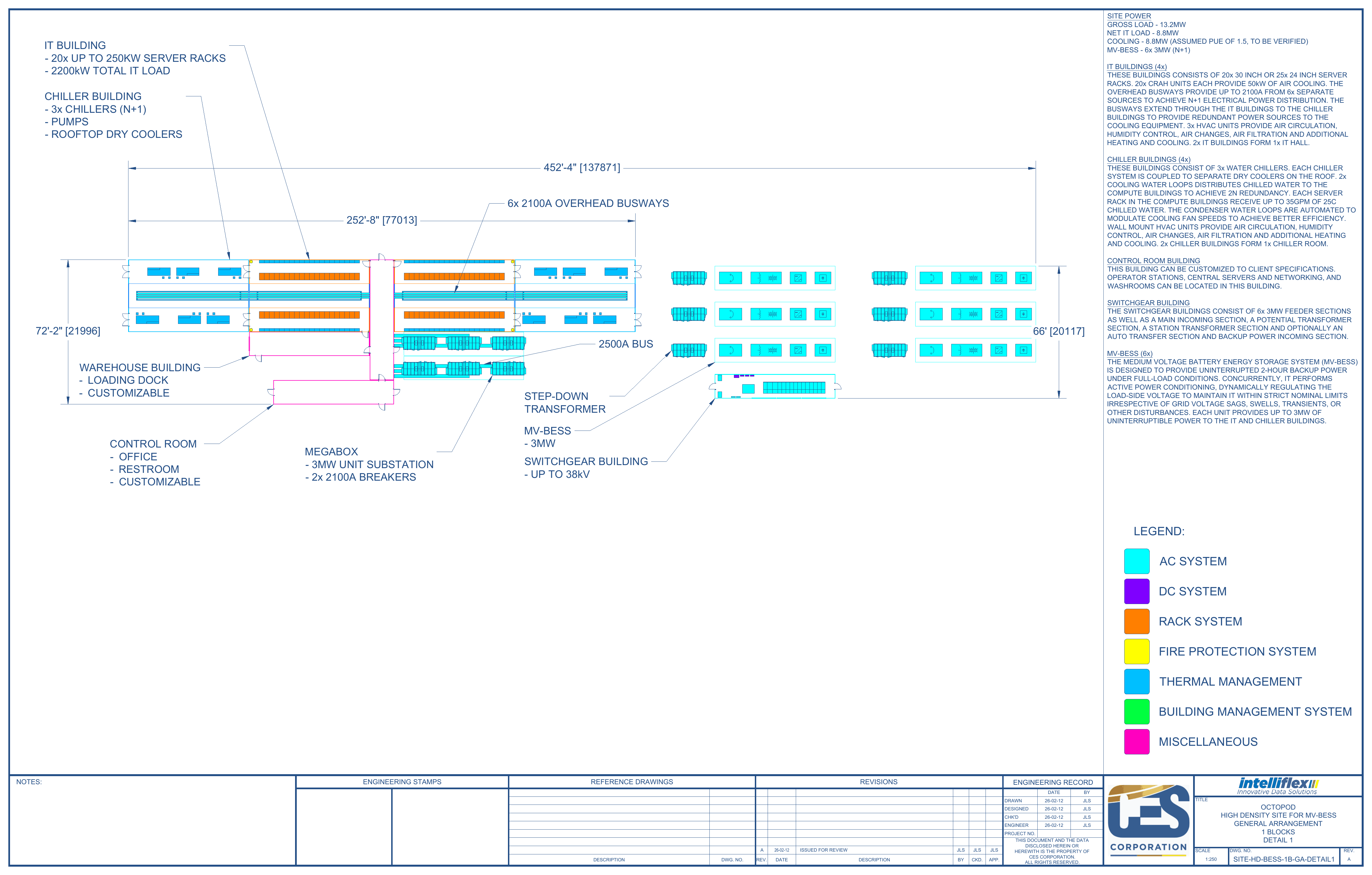
Follow the power in and the heat out. Click any step and it lights up on the plan above — the buildings it touches, and the direction it moves.
Utility arrives at the switchgear building
Rated up to 38 kV. Main incoming section, potential-transformer section and station-transformer section, with an optional auto-transfer section and backup-power incoming. From here the site splits into 6 × 3 MW feeder sections.
Show it on the plan ↑Each feeder gets its own step-down transformer
Six transformers sit in the yard, one beside each MV-BESS enclosure, bringing the feeder down to the distribution voltage used by the batteries and the MegaBoxes.
Show it on the plan ↑MV-BESS holds the load and cleans the power
Six medium-voltage battery systems, 3 MW each, N+1. Each carries the site for 2–4 hours at full load and, at the same time, regulates the load-side voltage through sags, swells and transients. Each delivers up to 3 MW of uninterruptible power to the IT and chiller buildings.
Show it on the plan ↑MegaBox steps down to the building voltage
Six 3 MW unit substations in two rows of three under the IT hall, each with 2 × 2,100 A breakers on a 2,500 A bus (12.47 kV → 415 V per the single-line).
Show it on the plan ↑Six busways carry it overhead
Six 2,100 A overhead busways from six separate sources → N+1 at every rack. They run through the IT buildings and on into the chiller buildings, so the cooling plant shares the same redundant supply.
Show it on the plan ↑The racks do the work
Four IT buildings, 20 NVIDIA GPU rack positions each — 80 positions carrying 8.8 MW of IT load, which is 2,200 kW per building and an average of 110 kW a rack. Any one position can take up to 250 kW, so the power envelope — not the position count — sets the density, and the density follows the server class installed. SAVRN fills this envelope with 32 NVIDIA VR200 NVL72 racks at 250 kW, 8 MW of IT. Two IT buildings form one IT hall.
Show it on the plan ↑Heat leaves the rack in water and air
Each rack position receives up to 35 GPM of 25 °C chilled water. 20 CRAH units per building (50 kW each) handle the air side; 3 HVAC units per IT building manage circulation, humidity, filtration and air changes.
Show it on the plan ↑Chiller rooms reject it to the roof
Four chiller buildings, 3 water chillers each (N+1), every chiller coupled to its own rooftop dry cooler. Two chilled-water loops serve the compute buildings (2N). Condenser loops modulate fan speed for efficiency. Two chiller buildings form one chiller room.
Show it on the plan ↑Operate and supply
The control room holds operator stations, central servers and networking; the warehouse has the loading dock and stays customizable. Both open onto the corridor between the halls.
Show it on the plan ↑Redundancy, with the arithmetic
What the N+1 and 2N on the drawing mean for this block.
| Element | Quantity | Scheme | What it means |
|---|---|---|---|
| Power feed | 6 × 3 MW feeder sections | N+1 | 18 MW installed against 13.2 MW gross. One section out → 15 MW still covers the block. |
| MV-BESS | 6 × 3 MW | N+1 | 2–4 hour backup at full load plus continuous voltage conditioning. One unit out → 15 MW. |
| MegaBox | 6 × 3 MW unit substations | N+1 | One per busway; 2 × 2,100 A breakers each. |
| Overhead busways | 6 × 2,100 A | N+1 | Six separate sources into each IT building; extended into the chiller buildings. |
| Chillers | 3 per chiller building (12 total) | N+1 | Each chiller has its own rooftop dry cooler. |
| Chilled-water loops | 2 loops | 2N | Either loop can carry the compute buildings. |
| HVAC | 3 units per IT building | — | Circulation, humidity, air changes, filtration, supplemental heat/cool. |
Building schedule
Footprints are scaled from the 1:250 geometry; the dimensioned figures on the plan (452′-4″, 252′-8″, 72′-2″, 66′) are as drawn.
| Building | Qty | Footprint | Contents / rating |
|---|---|---|---|
| IT buildings | 4 | ≈60′ × 36′ per hall (two buildings) | 20 rack positions · 2,200 kW IT (110 kW average, up to 250 kW at a position) · 20 CRAH × 50 kW · 3 HVAC · 6 busways |
| Chiller buildings | 4 | ≈60′ × 36′ per room (two buildings) | 3 chillers (N+1) · pumps · rooftop dry coolers · 2 loops |
| Corridor | 1 | ≈12′ × 60′ | Links halls, warehouse and control room |
| Warehouse | 1 | ≈60′ × 12′ | Loading dock · customizable |
| Control room | 1 | ≈60′ × 12′ | Office · restroom · operator stations, servers, networking |
| MegaBox | 6 | two rows of three under the IT hall | 3 MW unit substation · 2 × 2,100 A breakers · 2,500 A bus |
| MV-BESS | 6 | ≈60′ × 12′ enclosures, three rows of two | 3 MW · 2–4 h full-load backup · power conditioning |
| Step-down transformers | 6 | beside each MV-BESS | one per feeder |
| Switchgear building | 1 | ≈60′ × 12′ | up to 38 kV · 6 × 3 MW feeders · incoming / PT / station sections |
The drawing
Full sheet, rendered as a blue-line. Drag to pan, use the buttons or pinch to zoom.
Drawing notes, as written
Transcribed word for word from the notes column of the sheet. Click a note and it lights up on the plan — the buildings that note is describing.
Site power
Gross load 13.2 MW. Net IT load 8.8 MW. Cooling 8.8 MW (assumed PUE of 1.5, to be verified). MV-BESS 6 × 3 MW (N+1).
Show it on the plan ↑IT buildings (4×)
These buildings consist of 20 × 30-inch or 25 × 24-inch server racks. 20 CRAH units each provide 50 kW of air cooling. The overhead busways provide up to 2,100 A from 6 separate sources to achieve N+1 electrical power distribution. The busways extend through the IT buildings to the chiller buildings to provide redundant power sources to the cooling equipment. 3 HVAC units provide air circulation, humidity control, air changes, air filtration and additional heating and cooling. 2 IT buildings form 1 IT hall.
Show it on the plan ↑Chiller buildings (4×)
These buildings consist of 3 water chillers. Each chiller system is coupled to separate dry coolers on the roof. 2 cooling-water loops distribute chilled water to the compute buildings to achieve 2N redundancy. Each server rack in the compute buildings receives up to 35 GPM of 25 °C chilled water. The condenser-water loops are automated to modulate cooling-fan speeds to achieve better efficiency. Wall-mount HVAC units provide air circulation, humidity control, air changes, air filtration and additional heating and cooling. 2 chiller buildings form 1 chiller room.
Show it on the plan ↑Control room building
This building can be customized to client specifications. Operator stations, central servers and networking, and washrooms can be located in this building.
Show it on the plan ↑Switchgear building
The switchgear buildings consist of 6 × 3 MW feeder sections as well as a main incoming section, a potential-transformer section, a station-transformer section and optionally an auto-transfer section and backup-power incoming section.
Show it on the plan ↑MV-BESS (6×)
The medium-voltage battery energy storage system (MV-BESS) is designed to provide uninterrupted 2-hour backup power under full-load conditions. Concurrently, it performs active power conditioning, dynamically regulating the load-side voltage to maintain it within strict nominal limits irrespective of grid voltage sags, swells, transients, or other disturbances. Each unit provides up to 3 MW of uninterruptible power to the IT and chiller buildings.
Show it on the plan ↑